Learn while you build
What is your code missing as a circuit?
Upload a sketch and we read which parts sit on which pins, then run it in your browser. After that we fill in what tends to go missing on the way to a breadboard. The 330Ω in front of an LED, the pull-down on a button. What went in and why is always written beside it.
What is built so far
How far one sketch travels, in real screens
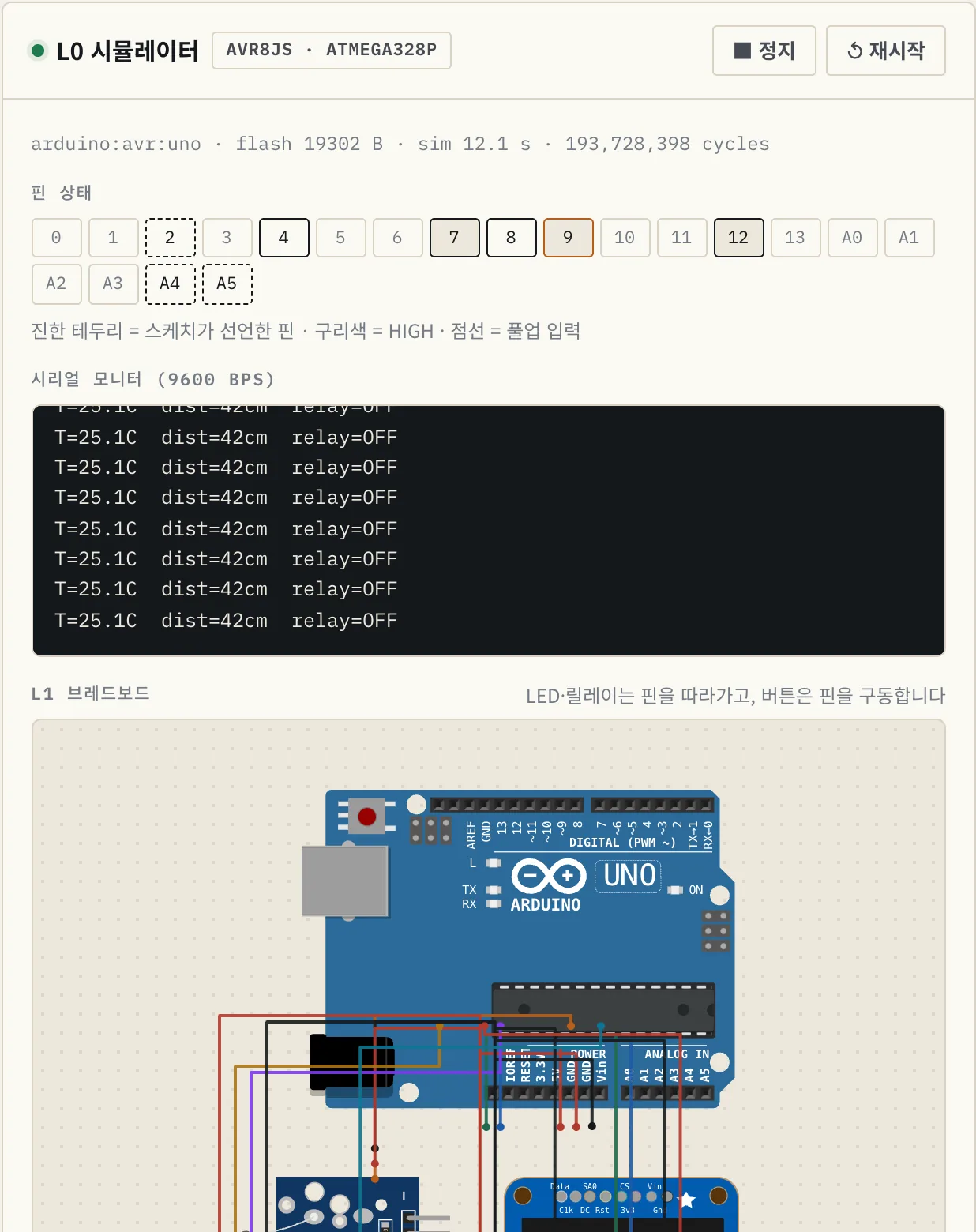
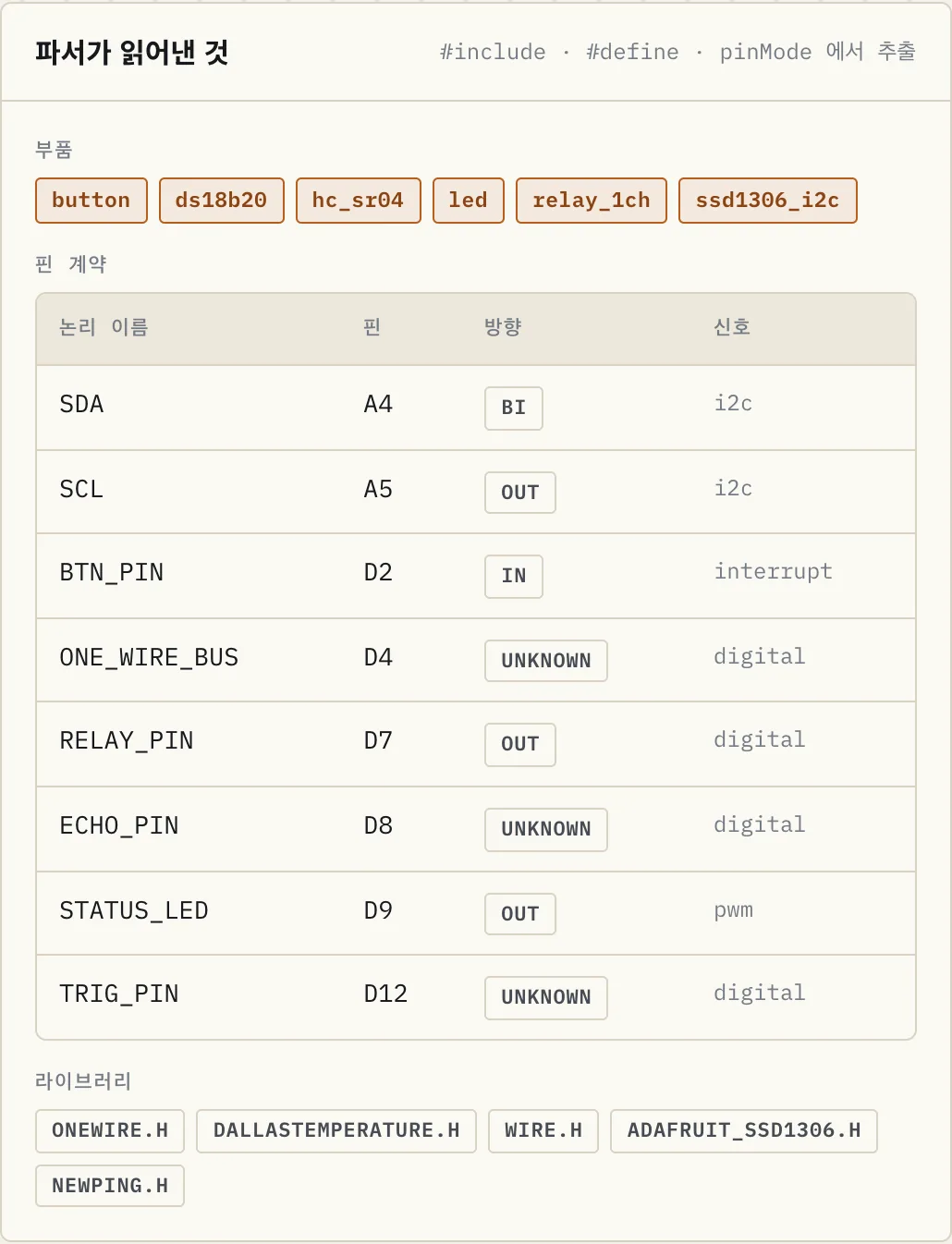
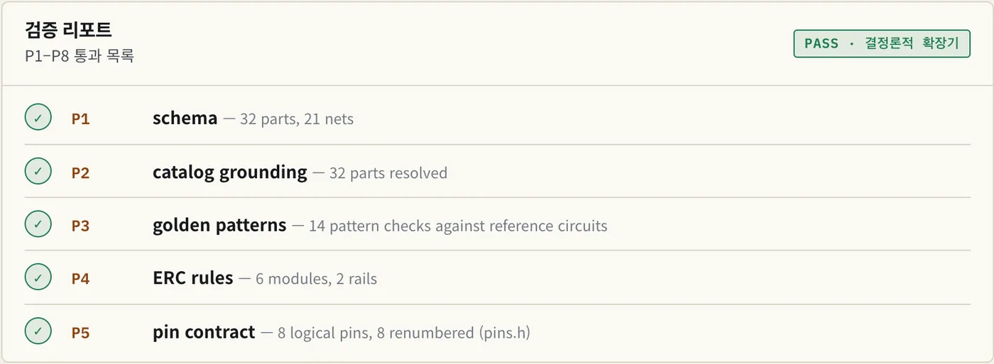
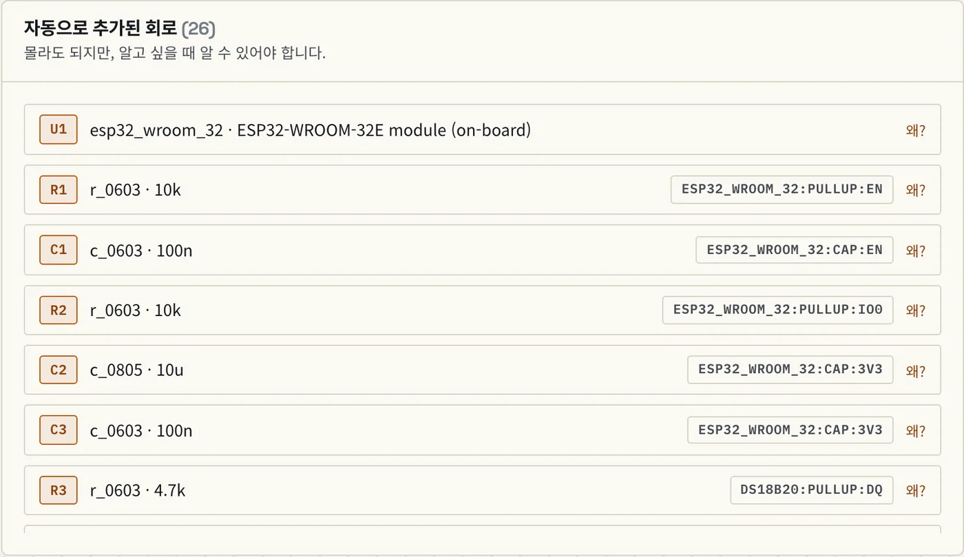
The six scenes below are not mockups. They are screens this site actually produced while working on the example uno_temp_relay.ino (a greenhouse controller: DS18B20, relay, OLED, ultrasonic). The first four you can use right now; the last two make the board and are not open yet.
Run the sketch as-is
The ATmega328P in your browser (avr8js) runs the .hex that arduino-cli built. Virtual DS18B20 and HC-SR04 answer over real 1-Wire and echo pulses, so the serial monitor shows T=25.1C dist=42cm.
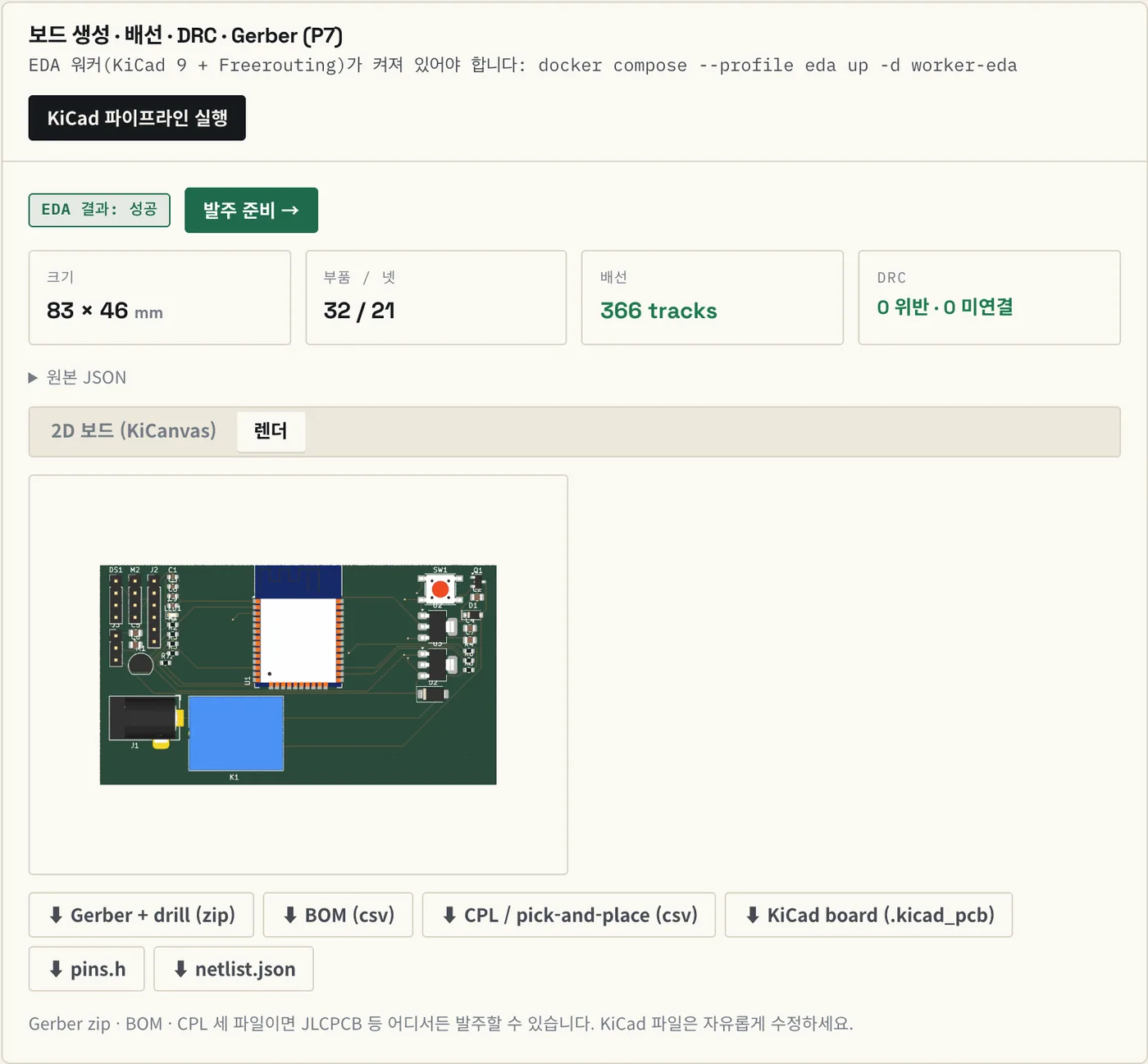
Captured 2026-09-08 · source Arduino Uno → target ESP32-WROOM-32E · verification P1–P5 PASS · board 63×49 mm · KiCad DRC 0 violations
The 4-level continuum
Simulator to breadboard, the stretch that is open
One project starts in the simulator and carries through to a breadboard diagram. Pin names stay the same as the level changes. L2 and L3, which make the board, are built but not open yet.
Zero hardware. Runs instantly in the browser on avr8js and rp2040js; ESP32 runs on server-side QEMU.
Runnable simulation · pin waveforms
A wiring picture of the modules inferred from your code, generated automatically and linked to the simulator.
Wiring diagram · parts list
Your first PCB. The form factor fixes the outline and connectors, so the hard decisions disappear.
Gerber · BOM · board render
ESP32-WROOM or RP2040 placed like a component. The module carries the certification (KC · MIC).
Gerber · BOM · CPL · certification checklist
Same project · same code · same pin contract
How it works
We never ask you to draw a circuit. We take the code you already have.
The #include list is the parts list. You create nothing new — you upload the sketch you already wrote.
The #include list is the parts list
Parts come from library includes and constructors; the pin contract and I²C addresses come from #define, pinMode and Wire.beginTransmission. We only ask about what cannot be inferred.
DallasTemperature.h → DS18B20Expand to a production circuit — and explain why
The dev board is replaced by an MCU module plus support circuitry. We fill in the power tree, decoupling, pull-ups, flyback diodes and level shifters, and attach a "why?" to every auto-inserted part. This is an educational product.
D1 1N4148 — relay coil back-EMFAI proposes, a deterministic verifier decides
An AI proposal cannot use parts outside the catalog and must pass golden patterns, ERC, the pin contract, N-sample consensus and KiCad DRC to be adopted. If any step fails we fall back to the rule-based expander. There is no AI in the verifier.
adopted_source: ai | deterministicWhat is missing, and why it is needed
Missing parts are filled into the breadboard drawing with the reason attached. An LED gets a 330Ω series resistor; a button read with pinMode(INPUT) gets a 10kΩ pull-down. If the sketch uses INPUT_PULLUP, the far leg goes to GND instead. The choice comes from the code, so the circuit never contradicts it.
R1 330Ω — limits the LED current on D13
#include <OneWire.h>
#include <DallasTemperature.h>

#define ONE_WIRE_BUS 4      // DS18B20 data
#define RELAY_PIN    7      // heater relay
#define LED_PIN      13

OneWire oneWire(ONE_WIRE_BUS);
DallasTemperature sensors(&oneWire);

void setup() {
  pinMode(RELAY_PIN, OUTPUT);
  pinMode(LED_PIN, OUTPUT);
  sensors.begin();
}

void loop() {
  sensors.requestTemperatures();
  float c = sensors.getTempCByIndex(0);
  digitalWrite(RELAY_PIN, c < 24.0);
  digitalWrite(LED_PIN, c < 24.0);
  delay(1000);
}- DS18B20 temperature sensorDallasTemperature.h · D4R3 4.7 kΩ 1-Wire pull-up inserted — datasheet value
- 1-channel relayRELAY_PIN 7 · OUTPUTQ1 NPN driver + D1 flyback — a GPIO cannot source the coil current, and the back-EMF at turn-off destroys the transistor
- LEDSTATUS_LED 9 · OUTPUT330 Ω series resistor — current limit
- ESP32-WROOM-32E (L3 target)Arduino Uno → module swapEN 10 kΩ pull-up + 0.1 µF, 3V3 10 µF + 0.1 µF — Espressif hardware design guidelines · confirmed on 4 Olimex boards
Three gates
Passing simulation ≠ safe to manufacture. So we never mix them.
Logic, electrical and physical are always shown separately. The moment you merge the three into one green light, you repeat exactly how breadboards betray beginners.
Does the code do what you meant? The browser sim records pin directions and toggles; the server re-derives the expectation from the sketch and only then passes the gate.
Will it survive? Voltage domains, I²C address clashes, current budget, flyback, decoupling, boot-strap pins — and KiCad DRC.
Does it really work? Power noise, EMI, sensor timing drift and part tolerances are invisible to a simulator. This gate only turns on when you tick it yourself.
The 8 electrical passesAll deterministic
| # | Pass | What it checks | Tool |
|---|---|---|---|
| P1 | Schema | Are parts, nets and pins structurally valid? | Pydantic |
| P2 | Catalog grounding | Does every part ID and pin name exist in the catalog? Hallucinations rejected on the spot | catalog |
| P3 | Golden patterns | Required support circuits per MCU, regulator and interface, extracted from real open-source boards | corpus/patterns.yaml |
| P4 | ERC rules | Voltage domains · I²C clashes · pull-ups · current budget · flyback · decoupling · boot-strap pins | rule engine |
| P5 | Pin contract | 1:1 mapping of logical pins · PWM/ADC/interrupt capability matches | pin contract |
| P6 | Consensus | Majority agreement of N normalized AI topologies — otherwise fall back | N-sample vote |
| P7 | KiCad DRC | Generate board → route with Freerouting → kicad-cli pcb drc exit 0 | KiCad 9 · separate container |
| P8 | Sim regression | Recompile the same sketch for the target with pins.h applied; compare pin activity before and after | avr8js · rp2040js · QEMU |
P1–P6 run as unit tests without KiCad, P7 runs in a KiCad 9 container, P8 is browser simulation plus server comparison. An error at any stage means the proposal is not adopted.
It actually runs
Run an example sketch in your browser right now.
No login. Compiled on the server, executed in the browser on avr8js — with pin states, a serial monitor and virtual sensors attached.
Supported boards · modules
Start on 2 dev boards, land on 4 L3 targets, with 22 modules.
We recommend modules that already carry certification (KC · MIC) first, to remove the certification burden at design time.
Starting boards (L0–L2)
Production targets (L3 · module on board)
Each of the 22 modules ships a KiCad symbol and footprint plus a reference circuit with decoupling, pull-ups and protection already in place, with a plain-language explanation.
Pricing
Everything is free right now
The simulator, sketch analysis, the verification report and the breadboard diagram are all yours with an account. We will set prices when the board files open.
Free
Available nowEverything available today
- Unlimited simulator
- Sketch analysis and verification report
- Breadboard diagram with reasons
- 53 examples
Maker
Not yet openShield / HAT boards
- L2 conversion
- Gerber and BOM
Production
Not yet openModule on board
- L3 conversion
- CPL and certification checklist
Nothing is charged for the board side yet. We will say so again when it opens.
FAQ
Questions
Do I have to draw a circuit?
No. There is no schematic editor at all. Upload the .ino you already wrote or tick modules in the catalog, and we read the pin contract and parts list from the code. We only ask about what cannot be inferred.
Can I trust a circuit the AI made?
AI output is never used as-is. The AI only proposes; a proposal must pass catalog grounding → golden patterns (real open-source circuits) → ERC → pin contract → N-sample consensus → KiCad DRC to be adopted. If any step fails we fall back to the rule-based expander, and there is no AI in the verifier code. The report also records which proposal was adopted.
Which boards are supported?
Starting boards are the Arduino Uno and XIAO ESP32C3; L3 production targets are ESP32-WROOM-32E, ESP32-C3-WROOM-02, ATmega328P-AU and Raspberry Pi Pico (RP2040). Browser simulation covers AVR and RP2040; ESP32 runs on Espressif QEMU on the server. Raspberry Pi HATs come in a later phase.
Do I have to change my code?
Logical pin names stay as they are. If the MCU changes and physical pins move, we generate pins.h and show the change as a diff. The goal is a single #include "pins.h" line, and the P8 regression sim proves it by comparing pin activity before and after conversion.
Where can I use the generated files?
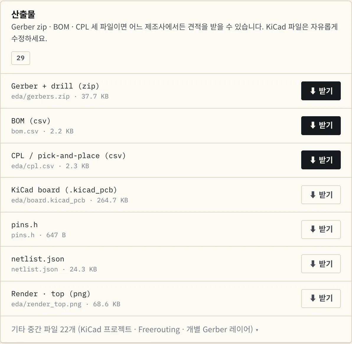
Gerber, drill, BOM and CPL are standard formats — any PCB tool or fab viewer opens them as-is. You also get the KiCad project, so you can keep editing in KiCad.
What about physical verification?
It is never passed automatically. Power noise, EMI, sensor timing drift and part tolerances are things the simulator and ERC/DRC cannot catch. The physical gate only turns on after you have checked the real board and ticked it yourself, and it is always displayed separately from the other two.
Start
One sketch is all it takes
53 examples are bundled, so you can arrive empty-handed. Upload one and we read the parts and pins and point at the missing circuit straight away.